In the era of technical progress and the increasing complexity of technical solutions, higher and higher requirements are placed on machine and devices parts which must be perfectly matched to other elements so that the whole mechanism works effectively and with maximum efficiency. That is why the cars produced today do not tolerate the slightest play or deviation from the dimensional standard.
How do you ensure that the requirements are met by the customer, the OEM and the car user implicitly, and deliver a part that will run smoothly and without excessive wear?
This requires highly efficient machining of high quality as well as measuring devices that allow the process to be monitored. Modern control and measurement systems can capture such fractional deviations, so that corrections can be made and losses can be eliminated.
How does the modern quality control system work?
In the past, when you thought about quality control, you would often think of a lonely worker who looks at every detail piece by piece and pushes aside the faulty ones. Currently, the approach to measurements has completely changed.
In the case of coordinate measurements, we do not measure the distance from point A to point B, but the values of the X, Y, Z coordinates of individual points on the surface of the measuring object. In most classical measuring machines, the measurement takes place in the Cartesian coordinate system, i.e. the movable measuring units of the machine move in three mutually perpendicular directions. The working body of the machine is the measuring head, while their position is measured by measuring rulers located in each axis of the machine or by encoders in the measuring head (in the case of 5-axis systems). On the basis of the recorded coordinates of individual measuring points, the machine computer determines the geometrical figures which the measured element consists of. The features of these figures are dimensions, and the distances of individual measurement points from defined reference elements are shape deviations.
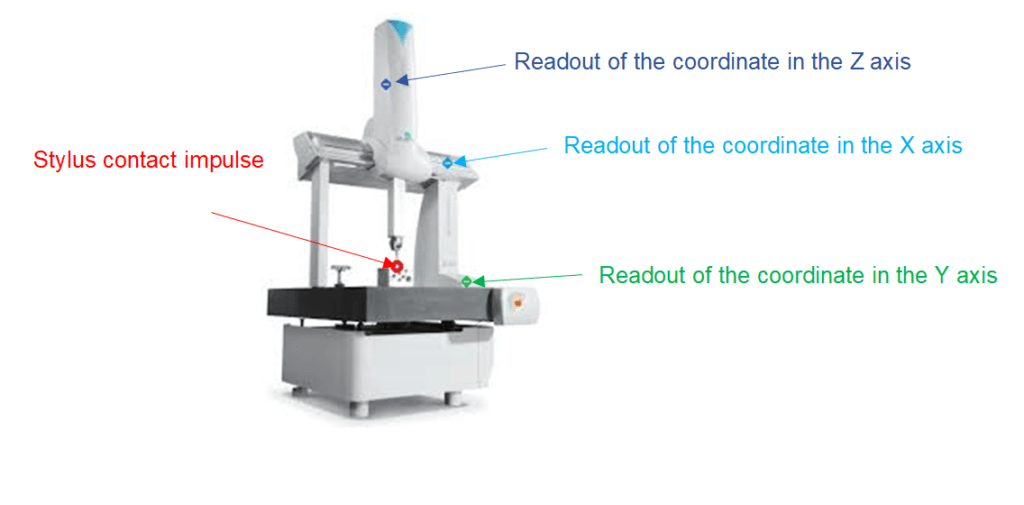
Scheme of reading the measuring point – the illustration used DEA Global Silver Performance Measuring Machine – source mechanik.media.pl
Types of measuring heads
Pulse – switching head – the pulse causes “reading” of the coordinates of the point from the measuring systems of the machine, mounted on its individual axes, and affects the drives and machine control.
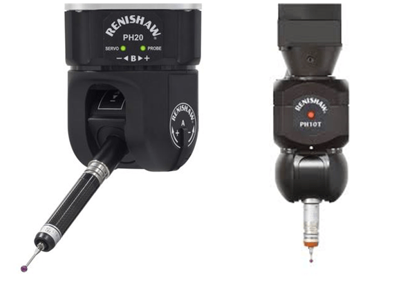
Impulse heads PH20 and PH10 – source renishaw.pl
Scanning – measuring head in passive and active versions (different in the way of applying the measuring force). The scanning head allows not only to detect the contact of the measuring tip with the surface of the measured object, but also to determine the coordinate values thanks to measuring transducers present in each of the axes. Thanks to this, the head measures the position of the tip in X, Y, Z coordinates with a resolution of 0.1 µm. During the measurement, the processed signal value from the transducers is added to the coordinates of the head position recorded by the controller, thanks to which it is possible, for example, to determine a map of shape errors deviations.
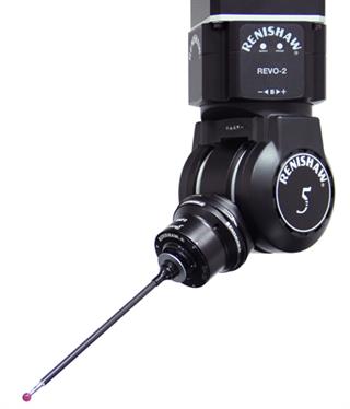
REVO-2 scanning head – source renishaw.com
Contactless – used for objects made of soft materials and some metal elements requiring less measurement precision. In their case, the location of the measurement point is carried out using laser triangulation heads or by analyzing the surface image from the head with a CCD camera. For triangulation heads, the basis for calculating the location of the measuring surface is a system of right-angled triangles. The laser diode emits a measuring beam of light which, when formed by the optical system, runs towards the surface of the measuring object. A spot with a diameter of several dozen to several hundred µm forms on its surface. The spot image is reproduced through an optical system on a photo line where the value is read.
Summary
There is no doubt that in the automotive industry, measurement on measuring machines is becoming a necessity. Fortunately, the choice of suppliers of such machines is wide, and the selection of the measuring method and machine depends mainly on the needs of the measurements, the size of the parts and the required accuracy of measurements – e.g. for most precise parts for drive systems or suspension, it is difficult to use contactless heads, which most often have too little accuracy.
A noticeable trend is the use of scanning heads at the expense of impulse heads. The development of scanning heads in many cases allows to achieve more accurate measurements through the number of collected points in a comparable, and sometimes even shorter time, and in the long run it seems to be a more economical solution, despite the initially higher investment price.
Measurement often turns out to be a “bottleneck” in the production process, therefore an interesting alternative to classic measuring systems on coordinate measuring machines is the 5-axis system. Based on our experience, thanks to the use of a 5-axis system, we were able to reduce the measurement time of a single part by 54%, which gave measurable benefits in the form of additional reserves in the area of measurements.
The scope of issues related to the measurement of parts is very extensive – I hope that the general outline of modern measurement methods can become an introduction to delving into this topic for those interested.
Jarosław Kondys

Become a CNC programmer right now!

Hello Everyone! My name is Jarosław Kondys and for almost 10 years I have been the Manager of Quality Department at Barosz. I successfully manage a team of quality engineers as well as a measurement team. A mechatronics technician by education, a quality expert out of passion. I am an enthusiast of motorization and visiting Polish castles.