I would like to invite you to read the last article of the Cutting Tutorial series. The topic will be my favourite machining method namely milling. Like other articles this one will also contain basic definitions related to the theme and some additional information facilitating the work of a technologist / programmer / setter.
Firstly, the basic theory – what characterizes milling? First, the tool performs a rotary motion, not the workpiece as it is in turning. Feed movement? It depends – usually the feed movement is also performed by the tool although it all depends on the kinematics of the machine tool itself and the number of axes involved in milling. A small digression – referring to the literature or searching for knowledge on the Internet about milling, you will find in 90% of cases the definition that the rotary movement is performed by the tool and the feed movement by the workpiece. How is it finally with this feed motion – tool or workpiece? Well, the old and good definition applies to milling on conventional machines. In case of CNC machines, the tool “paddles its own canoe” namely it performs the key role , i.e. it performs a rotary and feed 🙂
Secondly, cutting parameters. In the formula for cutting speed (the formula was given in the last article), the variable D in this case is the tool diameter. The feed per minute is the ratio of the feed per blade, the number of blades and the revolutions. The graphic presented below clearly shows what the feed really is (fig. 1). Choosing, for example, a cutter with the number of teeth three and not two we can significantly reduce the cutting time.
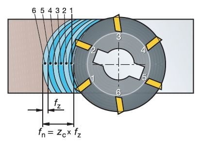
Fig. 1. Milling – feed [source: “Machining Handbook” Sandvik Coromant]
Thirdly – climb milling and conventional milling – which type of milling should you choose? The best choice is to program the tool movement to remove material from the “thickest chip” (fig. 2). Then the direction of the rotary motion is consistent with the feed motion – this is the climb milling. There are several cases when the choice is conventional milling, e.g. when there is a problem with vibrations we mill hard materials or there is a need to obtain a better surface roughness. Unfortunately, the big disadvantage of this type of milling is the much greater wear of the cutting tool.
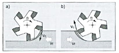
Fig. 2. Climb and conventional milling [source: “Operation and programming of CNC machine tools. Operator’s manual “W. Habrat]
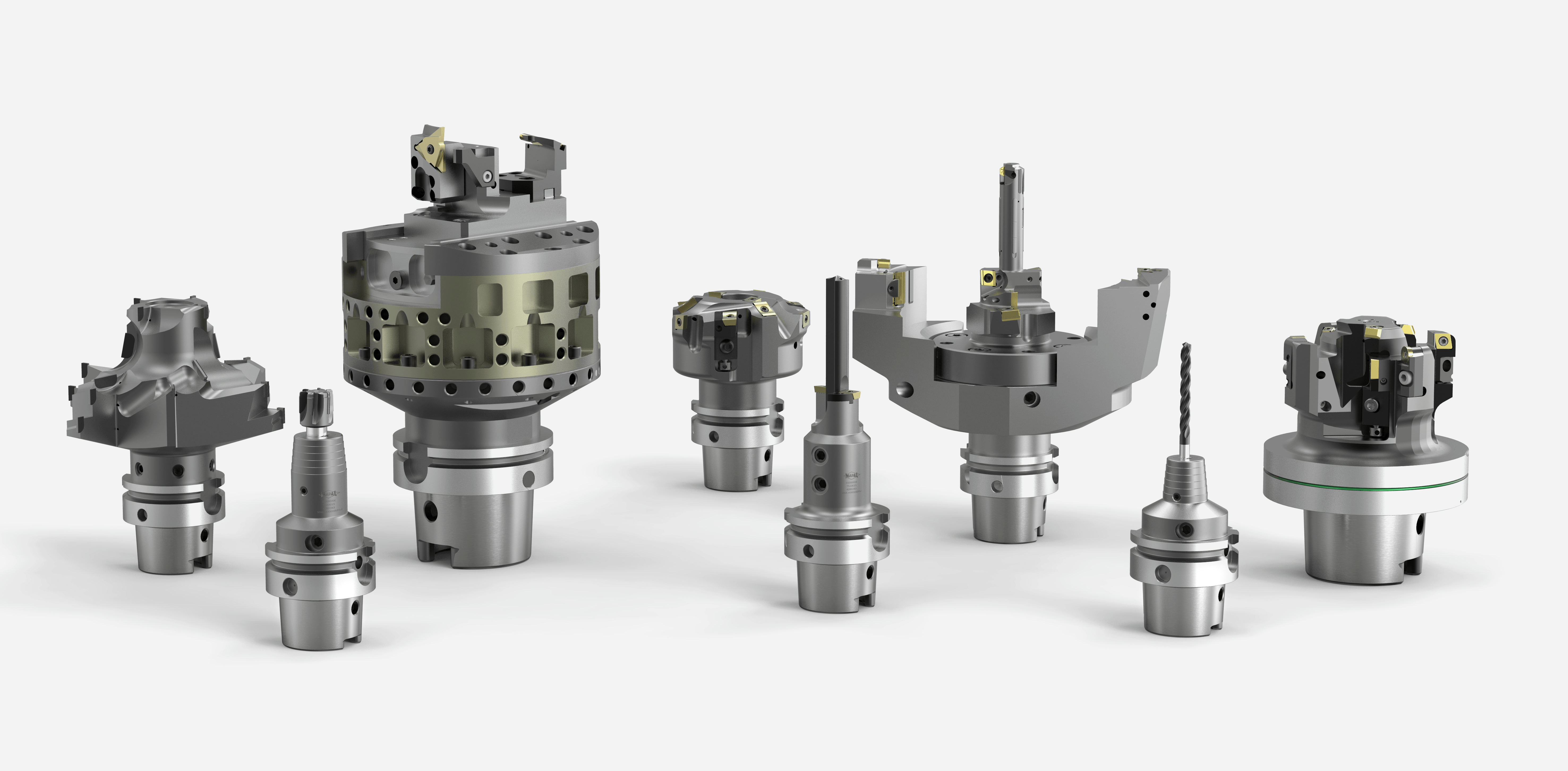
Starting the first article, I asked the question “which process is simpler – milling or turning?” Well, this time I will not answer perversely but directly – turning. Why? The number of variables in the milling process can cause dizziness. When programming simple turning, the X and Z axes are standardly used. In milling, however, there is a much wider range of possibilities – from simple counterboring in one axis, to travel and cutting in two axes, to profiling in three axes, even cutting in four or five axes continuously. Secondly, machines – milling machines are not only three-axis little devices, now they can be powerful machining centers, 4-axis, 5-axis, multi-spindle, with a turning function, with an extensive pallet system, technically advanced to meet the requirements that are unprecedented today. Of course, it’s not that modern lathes are not packed with technology because they definitely are but everything depends on the application. The last aspect is the tools. Which of them is more? Definitely milling ones. You can see it with the naked eye, e.g. when you look at a bookcase filled with catalogues from tool companies. “Turning tools” is usually one medium-sized catalogue – the rest are milling tools. The tools are diverse, ranging from simple milling cutters, milling heads to specialized multi-step counter bores or disc cutters (Fig. 3).
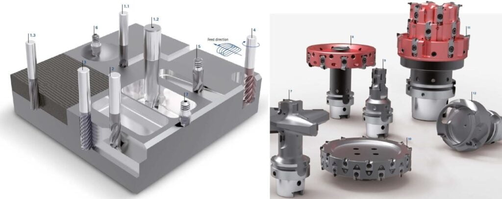
Fig. 3. List of milling tools. [source: Mapal’s tool catalog]
Finally, a few words about preventing vibrations in the milling process. Let me start with the obvious namely the reach. The shorter the better. There is a mysterious formula for deflection (take it easy, I won’t say it) where the length is to the third power! So really deflection and thus vibrations are strongly related and dependent on the length parameter. Another issue will be the selection of the appropriate mounting. When we want to minimize vibrations choose a heat shrinkable holder, and not, for example, Weldon.
It is generally about the contact surface, the larger the better. Above, I described the difference between climb milling and conventional milling. Conventional milling reduces vibrations but I emphasize once again – for use in exceptional situations because such milling contributes to the short life of the inserts. The last thing that can help is ‘High-Speed Machining’ track programming. It is a high-performance machining method with high parameters. The key to success is the constant optimal level of tool engagement. Therefore, cutting forces are low, tool wear is low and cutting time is significantly reduced.
The field of machining is extensive. While writing articles on basic machining techniques and describing their basic properties and relationships my goal was to to interest you in this subject. I hope my articles were at least a bit interesting and we’ll meet soon for more.
Natalia Matuszczyk
Cutting Tutorial – Turning
Effective metal processing thanks to MAPAL tools

Hello! My name is Natalia Matuszczyk. I am a technologist, CNC programmer and process engineer at Barosz. A big fan of new technologies and solutions that improve production in accordance with the Lean Management philosophy. I am devoted to my work and interests and work is my passion. I like challenges and I am not afraid to be a woman in the male machining world.